
![]()
Accreditations/Affiliations
I.A.S., ISO 17025
AASHTO AAP
AWS
I.C.C.
DSA
|
|
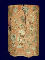
The concrete slab in a new facility exhibited excessive surface cracks. Testing Engineers was called in to determine the cause of this
These cracks are somewhat circular in orientation, and occur at all column locations. There are also cracks radiating from these circular areas. The cracks themselves range from hairline thickness to 1/8"±, and exhibit random patterns and directions. None of the cracks observed exhibited any measurable vertical displacement. The perimeter foundation has ties/dowels at 18" o.c., to tie the slab to the foundation. In addition, there are spread footings for the steel columns, approximately 8' x 8', squared to the exterior walls of the structure. There is no detail of how the slab is to be handled over these footings. An inspection of an adjacent tenant space provided a visual confirmation of the design details as they pertain to the slab, the perimeter foundation, and the column foundation pads. Reportedly, the shell of this structure was constructed under one contract, while the tenant improvement, including placement of the slab, was performed under a separate contract. The cracking is the result of plastic shrinkage, which occurs when the rate of shrinkage in the concrete exceeds the strength gain. While shrinkage in concrete is inevitable, there are mix-design and structural design considerations that can minimize this problem. The photo shows a core through the full depth of the slab, with the crack progressing through the concrete paste towards the bottom. Note that the crack does not bisect the aggregate; rather it passes around the stone. When the concrete is still gaining strength, the bond between the aggregate and the cement paste is not strong enough to pull the aggregate itself apart. The cracking of the slab around the steel columns may be attributed to a combination of joint placement and plastic shrinkage. If the joints immediately surrounding the column do not allow for shrinkage, the column will act as an anchor. As the slab shrinks, it pulls away from the column, leaving the corner "torn off". While it was originally thought that cracking might have been caused by pile-driving and/or adjacent demolition work, the type of crack found (and shown in the photo) is indicative of plastic shrinkage. Cracks caused by adjacent work would generally be through fractures as a result of differential settlement, impact, or bending. |
 |
Case Study: Dental Needle Failure
|
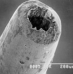
This case involved a fractured dental needle that was submitted to our laboratory for evaluation. The section of needle was reportedly removed from the patient after he had complained of continuous pain following a visit to his dentist. We were asked to determine the cause of failure of the needle. Metallurgical evaluation of the needle revealed that it met its specifications and did not have any inherent defects that may have contributed to the failure. This evaluation included microhardness tests, microstructural examination, and chemical analysis to identify the material.
Following the metallurgical evaluation, the fractured end of the needle was viewed at high magnification with a Scanning Electron Microscope. This examination revealed a failure mode typically caused by excessive tensile stresses. Refer to photos for electron micrographs of the fracture surface.
Based on our findings, it was concluded that the needed failed by high tensile stresses on the needle when the needle was extracted from the patients. The excessive stress may have been due to the needle being anchored between the teeth.
|
|
Case Study: Overturned Truck
|
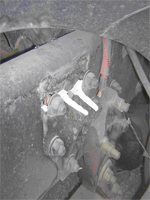
The cast suspension mounting of a big rig had fractured resulting in the fully loaded truck to lose its load. Testing Engineers were called in to determine the cause of failure of the mounting.
Reportedly the truck was not overloaded and was not being driven with excessive speed.
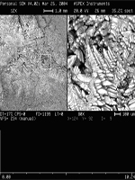
Initial field examination of the mounting revealed a clean and uniform fracture indicating that fractured had occurred instantly and was not a gradual process commonly associated with fatigue. Laboratory examination of the fracture surface with a high magnification microscope revealed high levels of porosity within the casting. Photos 1 and 2 are views of the fractured mounting and high magnification views of typical porosity. The needle-like structure is due to fast cooling following casting and is typical of casting porosity.
In conclusion, inherent casting defects, that made the mounting more brittle, was the major contributing factor in its failure.
|
  |
Additional Case Studies:
Testing Engineers | 2811 Teagarden St., San Leandro, CA 94577 | P: (510) 835-3142 | F: (510) 834-3777 | E-mail Us At: info AT testing DASH engineers.com